The use of Brushless DC (BLDC) motors is increasingly common nowadays because of its advantages over the universal brushed DC motors. A few features that the BLDC over the brushed DC motors are:
§ Better torque-speed characteristics
§ High dynamic response
§ High efficiency
§ Long operating life
§ Noiseless operation
§ Higher speed ranges
In addition to these features, the BLDC has a good torque to size ratio. This makes it a prime option in applications where the weight and space are critical factors, such as e-bike solutions.
Unlike a brushed DC motor, the commutation of a BLDC motor is electronically controlled. Powered through DC, BLDC motor is driven through a 3-phase model. The stator windings should be energized in a sequence to rotate the BLDC motor. In this case, the rotor location is important to determine which winding should be energized in sequence.
The Hall Effect position sensor is another essential tool in a BLDC and used most often in applications with great variation in starting torque or requirement of a high initial torque. The proper sequence for commutation can be found by reading signals generated from the sensors embedded in the rotor.
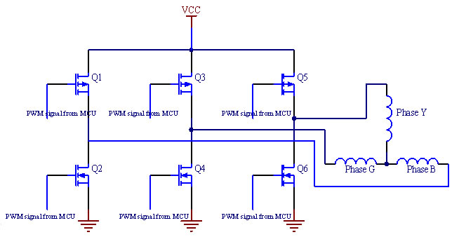
Figure i: 3-phase Half-Bridge Driver for 3-phase BLDC motor.
Control of a BLDC motor with position sensors can be achieved through the use of micro-controllers with ADCs and timer with PWM outputs, while an embedded Flash size of 4-16KB to accommodate the algorithms for motor control. The solution that WPG works on adopts ATMEL’s AVR microcontroller ATmega169p which we deem adequate for the application.
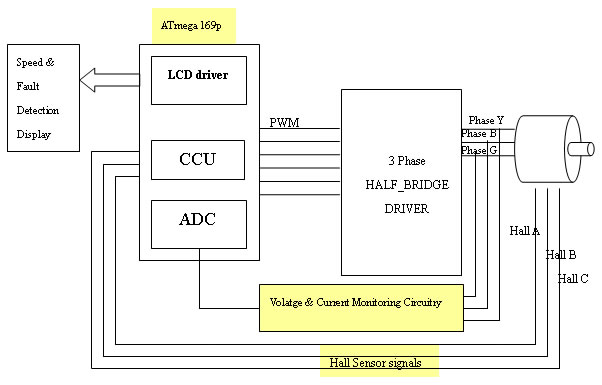
Figure ii: 2 Block diagram of Micro-controller controlled BLDC
The ATmega169p is a low-power (pico-power) CMOS 8-bit microcontroller based on the AVR enhanced RISC architecture. By executing powerful instructions in a single clock cycle the Atmega169p achieves up to 16 MIPS throughput at 16 MHz allowing the system designer to optimize power consumption versus processing speed.
In this application, a 16-bit timer TIMER1 of ATmega169p is used for PWM output generation. An 8-bit timer TIMER0 is used as a counter for speed measurement. Speed measurement can be achieved by counting event of Hall-effect sensor signal changing.
Atmega169p also comes with an On-chip 4x25 segments LCD driver controller with internal setup voltage making it useful for cost-effective applications. Simple display functions such as over voltage and current monitoring, speed display and direction indications can be achieved by Atmeag169p’s on-chip LCD driver, reducing the component count.
By combining a 8-bit RISC with In-system self-programmable flash, on a monolithic chip, the Atmega169p is a powerful microcontroller that provides a highly flexible and cost effective solutions to many embedded control applications.
Our intention for such development has been to provide a solution for E-Bike. There are 2 main components for the E-Bike solution, the motor control which we have discussed, and the battery charging function which is the other essential part of the whole solution. Although ATmega169P is a suitable candidate for the solution due to its functionality versus its cost, it still has the capacity to handle the battery charging portion, which will be presented in our future publications.
Wirtten by Tin Tin Naing
Edited by Siew C.H.